Understand why thin walls disappear in a preview
Find out whether a missing wall comes from scale, geometry or the way toolpaths are generated.
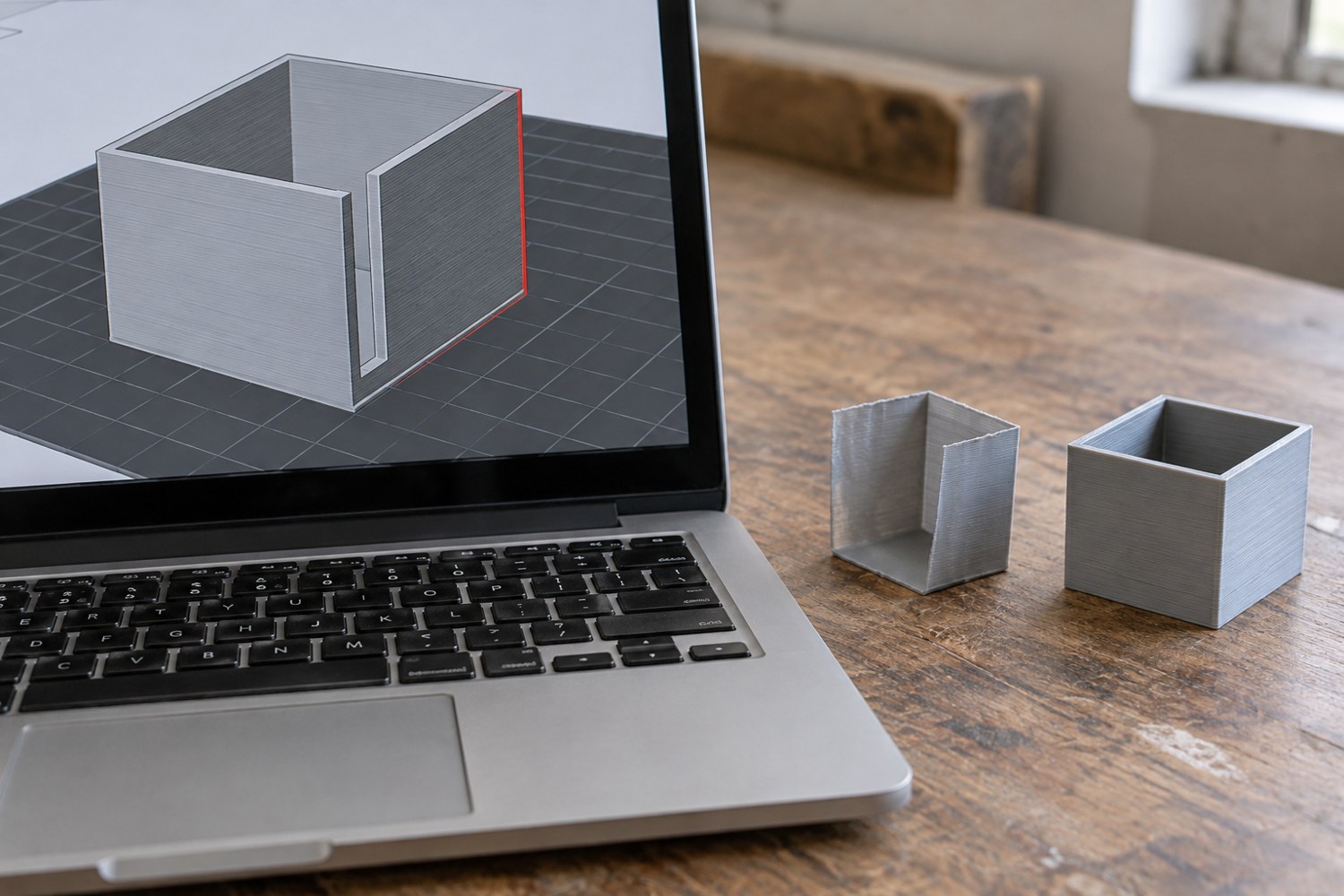
A fine wall can be visible in the model view and absent from the sliced preview. This is not a reason to start printing and hope that the machine fills the gap. The preview is telling you that the selected slicing setup has not produced the expected path. Begin by identifying the exact feature: an architectural partition, a raised letter or a narrow rim around a base.
Measure the feature in the model rather than estimating it from the screen. Check the imported units and overall dimensions first. If the entire building arrived at one tenth of its intended size, changing advanced wall settings addresses the wrong problem. Compare a known dimension, such as the base width, with the design notes.
Follow the missing region through the layers
Use the layer control to see whether the feature disappears everywhere or only at its narrowest point. A tapered wall may remain at the bottom and vanish near the top. A decorative groove may remove enough material to divide a wall into separate islands. Save a screenshot of that transition, then compare it with the actual mesh rather than relying on a smoothed shaded view.
Different perimeter strategies can treat narrow geometry differently. PrusaSlicer's Arachne generator varies extrusion width, but it still has a minimum feature threshold; features below that threshold are not printed. Its documentation also explains that the older thin-wall control is not used in the same way with Arachne. Check the documentation for your installed version instead of hunting for a checkbox described for a different slicing method.
Before changing those settings, ask whether the intended feature would be useful if printed. A barely visible partition may be too fragile to survive handling or painting. Making the geometry slightly more substantial can be a clearer design choice than forcing an extremely narrow path. If dimensions are fixed by a mating component, redesign the neighbouring detail rather than enlarging the whole object.
Choose one testable correction
Try a supported alternative profile, a deliberate wall-thickness revision or a compatible nozzle choice, one at a time. Re-slice and inspect the same region. Record whether the path has appeared and whether nearby holes remain open. A setting that restores one thin wall may also change the dimensions of other small features, so the successful preview is the beginning of the check.
Print a small section that includes the corrected wall and the surface beside it. Handle it in the way the finished model will be handled. If the feature breaks during ordinary cleanup, return to the design. If it survives but disappears under primer, decide whether more thickness or a different finishing approach is appropriate.
Keep the original and revised files separate. Name the changed dimension in the revision note rather than describing the result as “fixed.” The useful outcome is a feature that exists in the toolpath and remains useful in the finished object. An attractive screen rendering, an advanced setting and a successful extrusion are three different stages of that judgement.
Check whether the source contains real thickness rather than only a surface. Some visual models are designed for rendering and contain sheets that look solid under shading but do not describe the volume expected for manufacturing. Inspect the geometry in the modelling application and use its analysis tools with the documentation for that application. Automatically repairing a file can change details, so compare the repaired version with the original before assuming the missing wall has been solved.
For repeated details, correct one representative feature and test it before applying the change throughout the model. A building with dozens of similar windows is a good candidate: a small revised façade can establish readable proportions without committing the entire file to an untested enlargement.
Another detail to explore
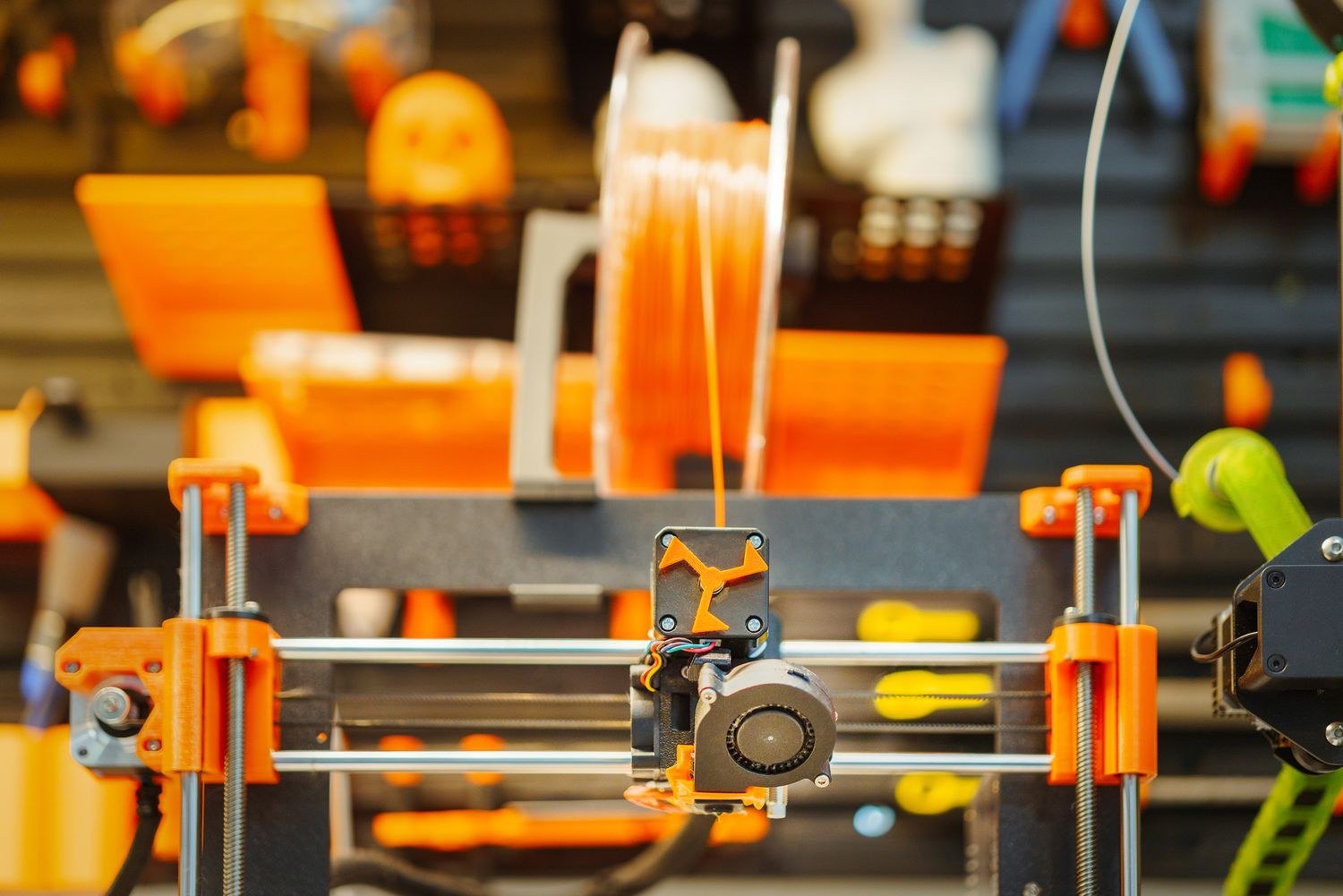
Choose a first 3D printer around the objects you want to make
Start with three objects, their dimensions and the space available for making them. Those decisions narrow the printer search before speed claims do.
Read article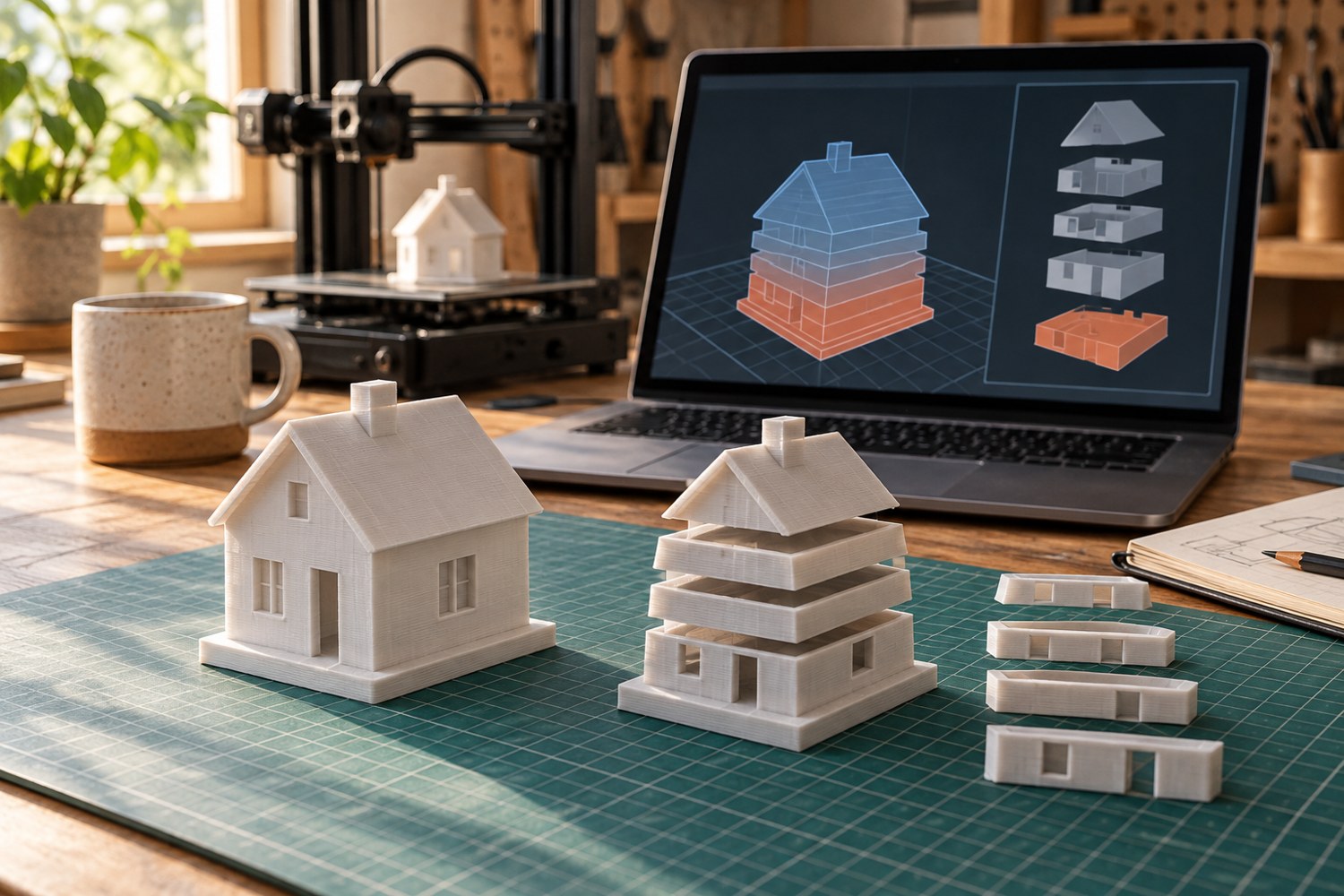
Read a sliced preview before starting a print
Read the toolpaths, first layer and delicate features before a file reaches the printer.
Read article