Read a sliced preview before starting a print
Read the toolpaths, first layer and delicate features before a file reaches the printer.
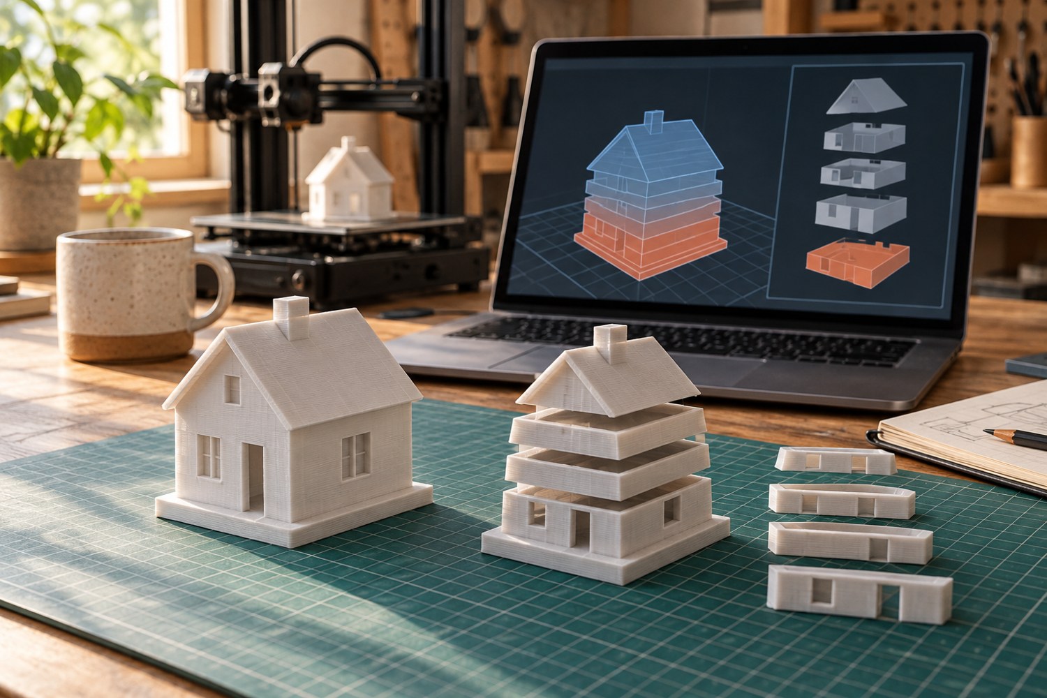
A model can look complete in the editing view and still produce an unsuitable print. The editing view describes the shape you imported; the sliced preview describes the paths the printer is being asked to follow. Checking the latter is especially useful for a miniature building with window openings, a hollow roof and narrow railings. Those features need different kinds of attention, even though they belong to one object.
Begin with the profile names. Confirm the intended printer, nozzle and material before studying a beautiful set of coloured lines. A preview cannot make a file prepared for the wrong machine appropriate. If you received ready-made G-code with a model, obtain the editable geometry and slice for your own equipment unless the supplier explicitly documents compatibility with your exact setup.
Follow the object from the floor upwards
Move the layer control to the beginning and identify every footprint touching the plate. A little tower beside the main building may be an intended separate component, a support, or an accidentally detached fragment. Compare it with the assembly drawing. Look for a continuous outline where a wall should start and an opening where a hole should remain clear. Rotating the full-height object often conceals this information.
Then advance through the model in stages. Stop at the first window lintel, the underside of a balcony and the start of the roof. Ask what lies beneath each newly appearing feature. This is a geometry check rather than a promise that every supported line will print perfectly. A support column that exists in the preview may still be awkward to remove from a sealed cavity.
Use the preview legend rather than assuming that a particular colour always means the same thing. In PrusaSlicer, for example, different views expose features and movement information, and the G-code viewer can identify profiles and simulate paths. Externally generated files may contain less information. A missing classification should be treated as missing information, not evidence that a feature is harmless.
Inspect the features you will use
Zoom into the mounting holes, mating edges and small lettering. Compare the intended shape with the actual lines. A decorative railing that vanishes entirely needs a model or slicing change before printing. A hole partially filled by support requires a removal plan. On an enclosure, check the interior as carefully as the exterior: a tidy outside is little help if an internal rib occupies the space needed by a connector.
Finally, inspect the last few layers and the overall time and material estimate. Save the project with the chosen profiles, then export a clearly named print file. If the filename on the printer differs from the one you just inspected, stop and resolve that mismatch. Keep one screenshot of a critical layer when testing a revised design; it provides a precise comparison after the physical part is finished.
This review can be short for a familiar flat part and much longer for an unfamiliar assembly. Its value comes from finding specific contradictions: a missing wall, an unsupported start, a blocked hole or the wrong machine profile. Merely watching an attractive animation from start to finish is less informative than pausing at the features that determine whether the object can be assembled.
Another detail to explore
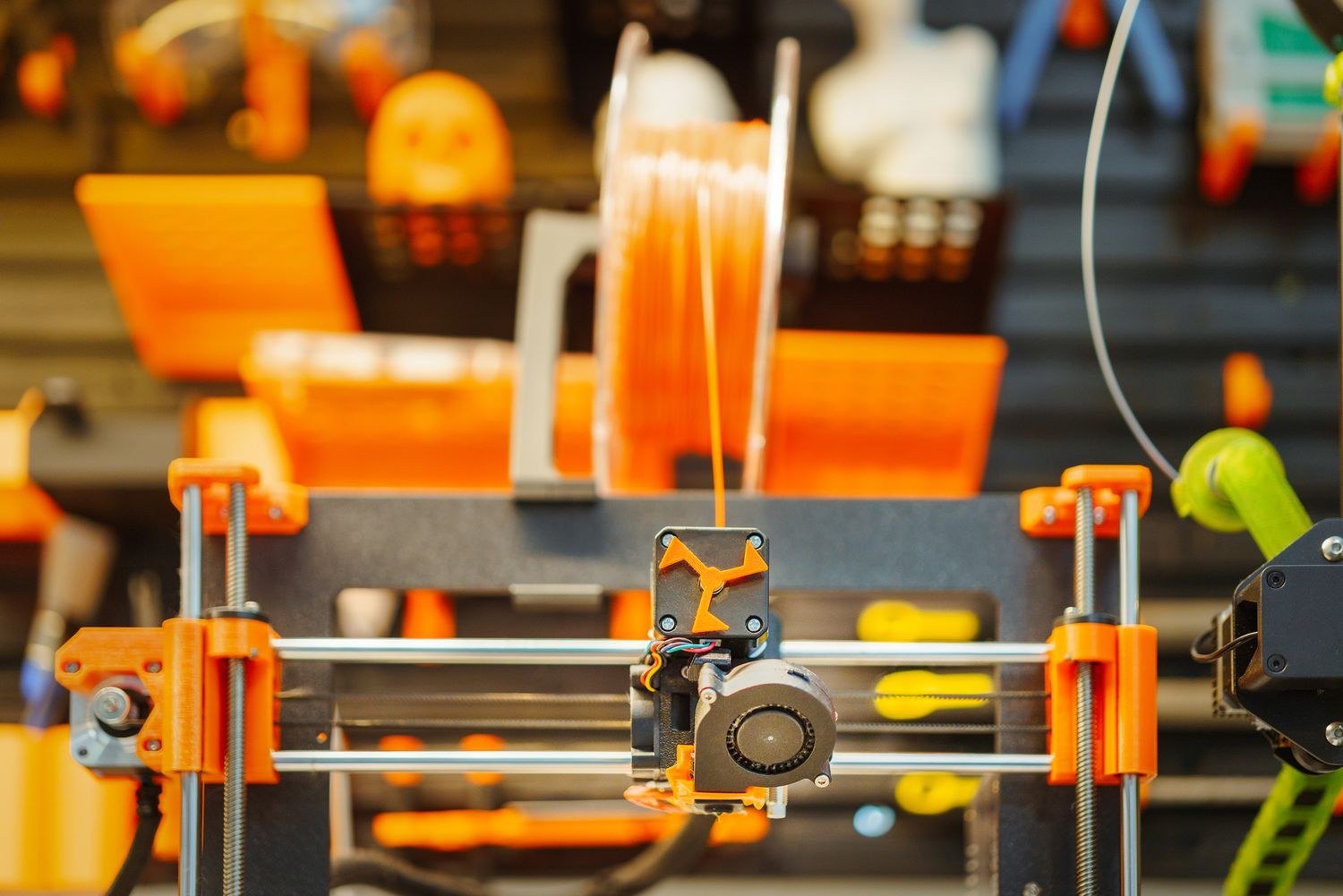
Choose a first 3D printer around the objects you want to make
Start with three objects, their dimensions and the space available for making them. Those decisions narrow the printer search before speed claims do.
Read article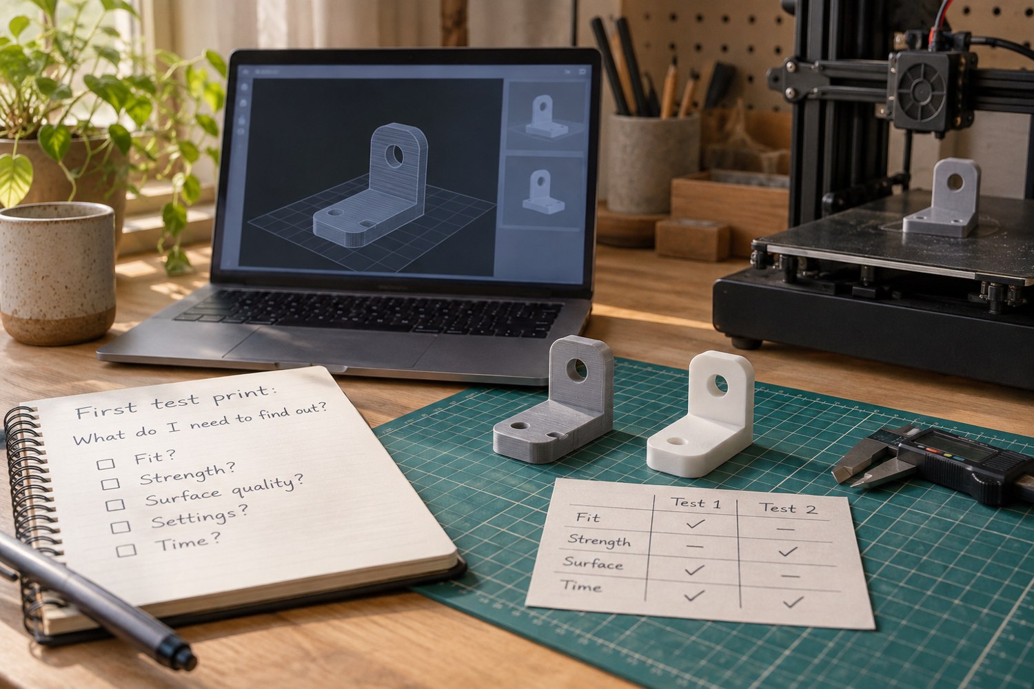
Plan a first test print with a clear question
Choose a small experiment that answers one question about your printer or model.
Read article