Print a fit test before a full-size enclosure
Use a short section of the real enclosure to check fit, access and finishing allowance.
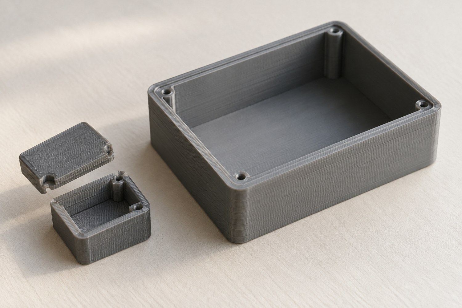
A full enclosure can take hours to print before revealing that its lid binds or a connector cannot pass through the opening. A fit test reduces that risk by retaining the important interface and removing the rest of the volume. Choose the interface carefully: the rim, one corner, a screw boss or a connector opening may each need a different sample.
Start with a drawing of the parts that must meet. Record the actual component dimensions and the model revision. Decide whether the fit should slide freely, locate loosely or hold with a separate fastener. Those goals require different clearances, and there is no single gap that suits every printer, material and shape.
Preserve the conditions that matter
Keep the test section in the same orientation as the full enclosure. Retain the wall thickness and nearby features that influence the joint. A loose pin printed vertically may not represent a horizontal pin integrated into a wall. If you crop the model, inspect the new cut edges so that they do not introduce an unrelated printing problem.
Make two or three labelled clearance variants when the starting value is uncertain. Change the dimension deliberately and record whether it is a gap on each side or a total difference across the part. Confusing those two conventions can double the intended clearance. Place identifiers away from the mating surfaces so that the labels do not alter the test.
Let the pieces reach their normal handling condition, remove only the support or brim that the full part would also lose, and test gently. Do not force a tight sample until it snaps and then describe it as a successful press fit. Note where it catches and whether the interference extends along the whole joint or occurs at a particular edge.
Check the assembly motion
A component may fit inside the final cavity but still have no route into it. Use the real part, with equipment unpowered where relevant, to check insertion and removal. Test access for fingers, screwdrivers and cables. A lid that closes only before a connector is attached may require a revised opening or a different assembly sequence.
If primer or paint will cover the joint, include a finished sample. If the joint should remain unpainted, mark that requirement in the assembly notes. Do not quietly sand one sample until it fits without recording the removed material; the full enclosure will otherwise repeat the same interference.
Once a variant works, transfer the measured design change to the full model and recheck the preview. A small coupon does not prove that a long wall will remain straight or that a large lid will be flat. It answers the local fit question. Keep that limitation beside the sample, then use the first full enclosure to check the larger geometry before printing a batch.
For a box containing several components, make a second kind of test: a shallow layout tray that preserves their positions but omits most of the walls. Place the real components in it and check connector direction, cable bends and fastener access. This answers a different question from the lid coupon. Keeping those tests separate makes a failure easier to interpret and avoids printing a complete enclosure simply to discover that two cables compete for the same corner.
Record which surfaces are intended to locate the component and which merely provide clearance. If every surrounding wall is treated as a precise locating face, small variations can make assembly unnecessarily difficult. A deliberate reference face and a little planned room elsewhere can produce a clearer design to test, without prescribing a universal clearance value.
Another detail to explore
Choose a first 3D printer around the objects you want to make
Start with three objects, their dimensions and the space available for making them. Those decisions narrow the printer search before speed claims do.
Read article
Read a sliced preview before starting a print
Read the toolpaths, first layer and delicate features before a file reaches the printer.
Read article