Split a large landscape model into printable tiles
Choose tile boundaries for assembly, appearance and handling, then verify that every exported piece retains its place in the landscape.
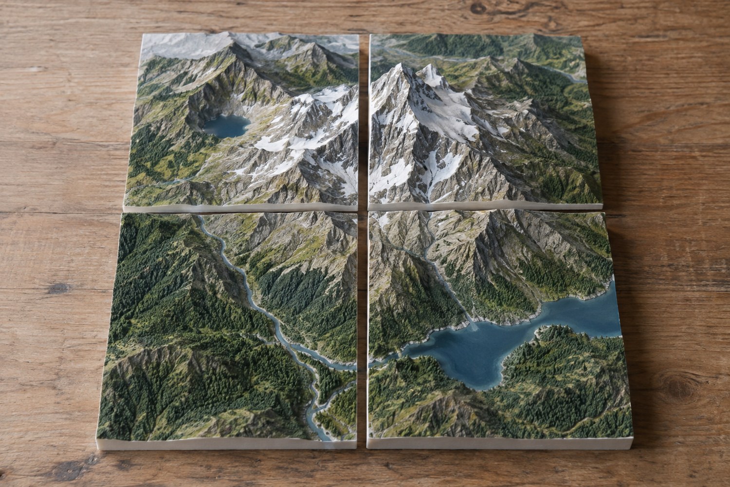
A large landscape can be divided into pieces that fit a smaller printer, but a grid imposed at the last minute can cut through the most awkward places. Plan the division while the main landforms are still simple. Draw the usable build area and a rough map of the completed scene side by side.
Start by identifying features that should stay intact: a building foundation, the entrance to a harbour or a narrow bridge support. A seam through one of these may make assembly harder or leave a visible mismatch. Place boundaries in areas that can be reached for fitting and finishing. A joint hidden behind a tall cliff is not necessarily a convenient joint.
Establish one reference plane
Give the landscape a common base level and record its overall footprint. If separate pieces have different underside heights without a deliberate reason, they may not sit together on a flat board. Check the assembled arrangement before moving pieces apart for export or printing.
Use a simple tile map with identifiers such as A1, A2 and B1. Put the same identifiers on file names and, where suitable, on an unobtrusive underside feature. Mark the front of the scene on the map. Similar-looking corners are much easier to confuse after they have been rotated onto separate build plates.
PrusaSlicer's cut tool can divide a model and create connector features. That capability can help prepare pieces, but it does not decide where a seam should go or how a large landscape will be supported. Keep those project decisions in your plan before using a particular tool.
Choose a joint that can be assembled
Decide whether the tiles are permanently attached to a common base or repeatedly rearranged. A permanent display may only need alignment during gluing. A modular set needs edges that tolerate handling and a way to identify the intended neighbours. Do not make every edge unique unless that limitation is deliberate.
Test one representative pair of edges, including any locating feature. Leave enough space for assembly and the intended finish. Consider the direction of insertion: a tile surrounded on three sides may not be able to slide into a joint that worked perfectly with two loose samples. Rehearse the assembly order on a paper map or simple block model.
Texture near a seam deserves special treatment. Large rocks that cross a boundary can make mismatches conspicuous. Keeping them separate until the tiles are fitted may give you more control. Conversely, a broad plain area can expose a straight line. Choose the boundary with the finished view in mind rather than assuming texture will hide every error.
Export and prove the arrangement
Save the complete assembled model before exporting individual pieces. Reimport the exports into a fresh scene and compare their dimensions and positions against the tile map. Check that all pieces are present and that no tile has been scaled independently.
Print a small boundary test before committing to the full landscape. Then make a low-detail dry assembly of the first complete pieces. Verify that the footprint still fits the planned board or case. Photograph the arrangement with the tile labels visible and keep that image with the project files. A manageable tile system should help both the printer and the person who eventually assembles, stores or repairs the scene.
Work through a four-tile example
Imagine a square island base divided into four pieces. The first sketch places a harbour building directly over the central crossing of the seams. Moving the building slightly onto one tile could simplify its foundation, while leaving the harbour water as the region where several tiles meet. This is a composition change made to support assembly, not a requirement that every scene use the same arrangement.
Now imagine one tile must slide sideways onto locating features while a cliff on its neighbour overhangs the joint. Draw the movement as an arrow and check the clearance along the whole path. Changing the order may solve the problem, or the connection may need to become a vertical drop-in relationship. A static assembled view cannot show this collision by itself.
Finally, place the four paper tile outlines inside the proposed storage box. Allow for protective separation and any projecting details. If the tallest tile cannot fit, decide whether its upper feature should be removable before it is modelled as one piece. The tile plan should remain useful after printing day, when the landscape has to be stored, transported or repaired.
Another detail to explore
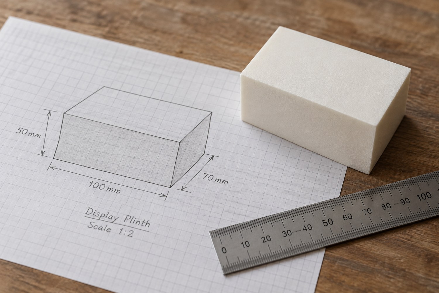
Start a model with dimensions instead of details
Build a short dimensional brief before adding bevels, textures or decorative features. It gives every later modelling decision a reference.
Read article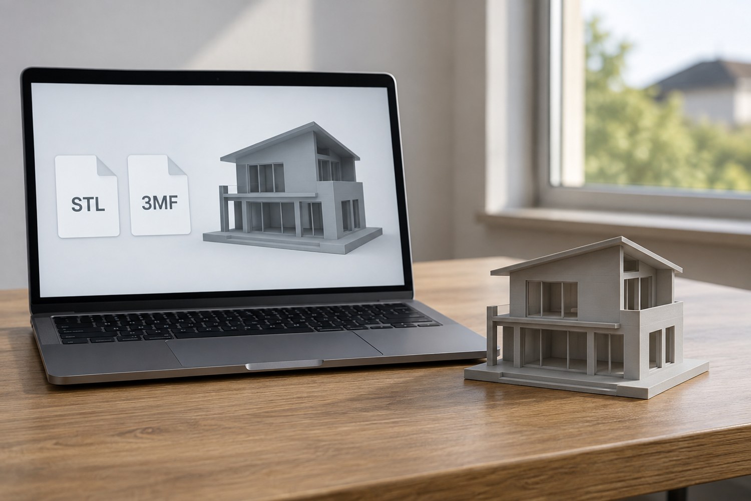
Understand STL and 3MF when sharing a print project
An STL mesh and a saved 3MF project can carry different information. Decide what a recipient needs before choosing the file to send.
Read article