Plan locating pins for a multi-part model
Locating pins help establish position, but their shape, spacing and assembly direction must suit the joint rather than merely decorate it.
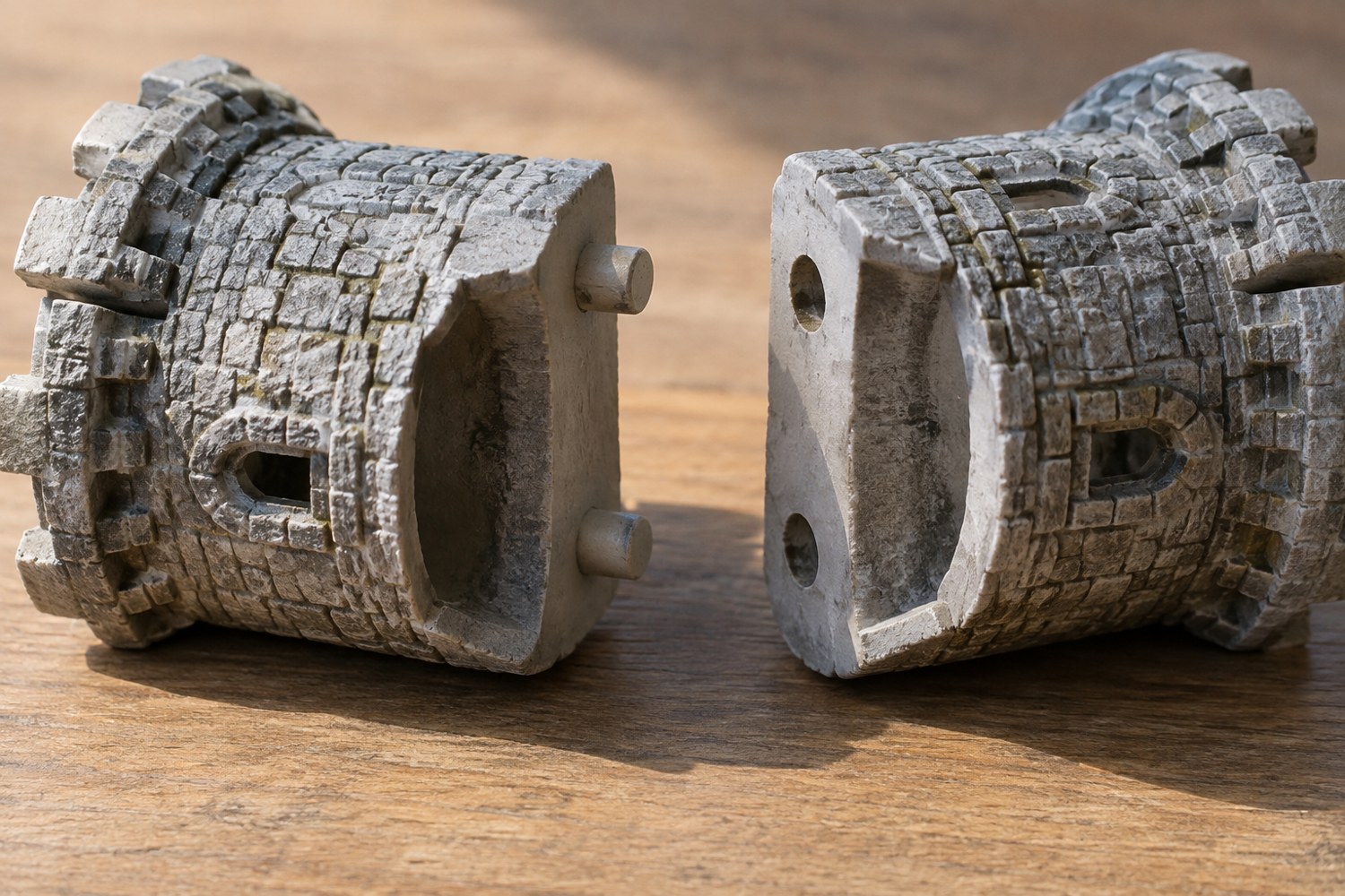
Before adding pins to a divided model, decide what they need to accomplish. They may align two halves during gluing, prevent a removable roof from shifting or identify the correct relationship between terrain sections. These tasks call for different fits and different access. A pin is not automatically a structural fastener.
Draw the join in section and mark the direction in which the pieces will come together. Check that the pin can enter its socket without the surrounding geometry colliding first. A joint that works when imagined as two flat slabs may be impossible once an overhang or wall is included.
Place the feature where material supports it
Avoid putting a socket directly behind a thin decorative surface. Leave enough surrounding material for the intended process and test the construction. A pin very close to an edge can also interfere with cleanup or leave a weak-looking strip. Its location should be chosen with the whole joint visible, not just the cut face.
Think about rotation. A single round pin may locate the centre while still allowing the parts to turn. A second locating feature or an asymmetric arrangement can establish orientation, but additional features also make alignment more demanding. Do not add a dense row of pins merely to make the model look engineered.
PrusaSlicer's cut tool offers connector options, including plugs and separate dowel-style pieces. These can help create geometry quickly. They do not remove the need to inspect fit, surrounding material and the route by which the model will be assembled. Keep the original model before applying a cut or connector operation.
Decide whether the pin should be separate
A separate pin can be replaced if it is damaged and may allow a different printing orientation. An integral pin reduces the number of loose components but can be awkward to repair. Compare these trade-offs for the actual model. A small scenic building that will be transported repeatedly may benefit from replaceable parts in exposed places.
Provide sufficient socket depth without making the pin bottom out before the visible seam closes. Include intended clearance and test it with a small pair of joint samples. Label the samples and retain the settings note. There is no single gap that guarantees the same fit across every material, machine and orientation.
Rehearse the final assembly
Dry-fit the unpainted pieces and inspect the visible surfaces. The joint should align the features you care about, not simply allow the pin to disappear into a hole. Check that there is a practical way to hold the pieces without pressing on fragile details.
If the joint will be glued, follow the adhesive instructions for the actual materials and leave room for the intended application method. If it will remain removable, evaluate repeated gentle assembly and removal before finishing. Keep paint out of the fit relationship unless the test explicitly includes it. Record the orientation of similar parts so that someone else can assemble them without experimenting with every possible combination.
Another detail to explore
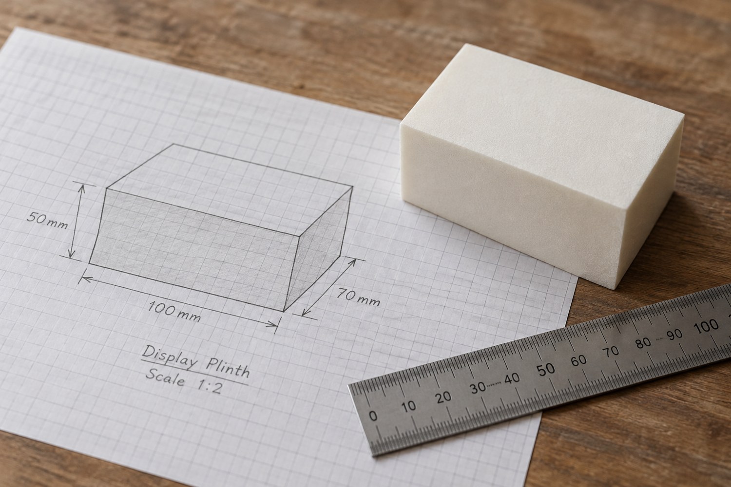
Start a model with dimensions instead of details
Build a short dimensional brief before adding bevels, textures or decorative features. It gives every later modelling decision a reference.
Read article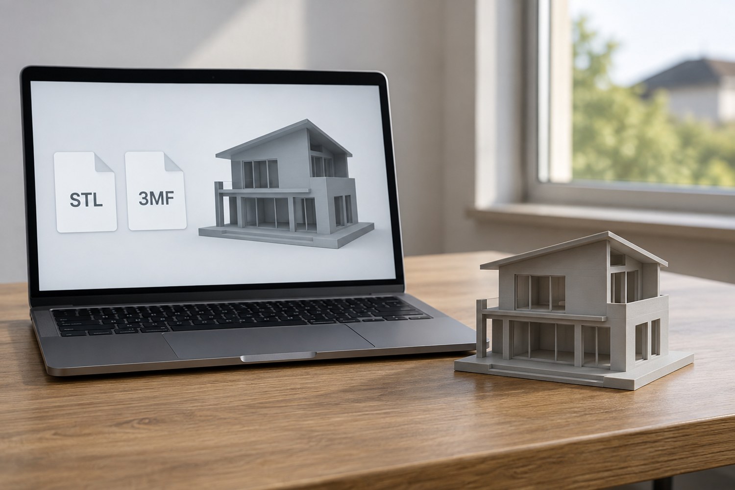
Understand STL and 3MF when sharing a print project
An STL mesh and a saved 3MF project can carry different information. Decide what a recipient needs before choosing the file to send.
Read article